
Phase Perfect - Quick Start Guide Installation
Enterprise Chassis Models
QUICKSTART PTE, Revision 003
Mounting dimensions
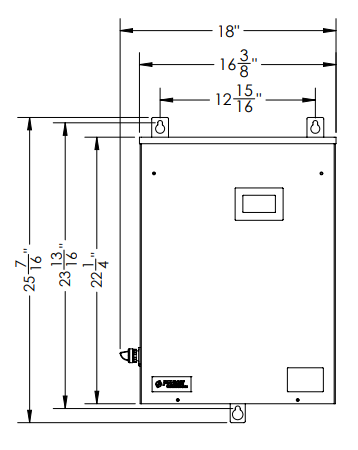
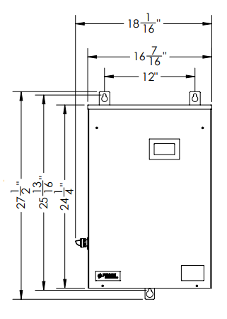
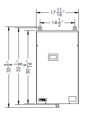
Mounting the Phase Perfect®
- Attach mounting brackets to back of unit with supplied hardware.
- Mount the unit to a solid, non-flammable surface capable of holding a minimum of 100 lbs. using the mounting brackets provided with the unit.
- Ensure air intake and exhaust openings are not obstructed. If mounted in a small room or cabinet, ensure temperature will remain below 40C (104F). Note: 18" (450mm) clearance below and 6" (150mm) around required for ventilation.
Connect Wiring
- Remove the cover by gently lifting and pulling forward after removing the screws on each side and front of the unit.
- Route cables through the supplied openings in the bottom of the enclosure, using appropriate conduit or strain relief devices.
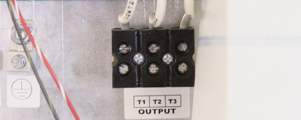
Note: Continuous metal conduit should be used for all power cables to reduce radiated electromagnetic interference (EMI). - Install the 3 load side conductors into the output terminals labeled T1, T2, and T3. Connect the load side ground conductor into the grounding terminal. Note: T3 is the manufactured leg on standard models. T2 and T3 are manufactured on voltage-doubling models.
Suggested Breaker Sizes
| PTE407 | PTE410 | PTE007, 207, 415 | PTE010, 210 | PTE015, 215 | PTE020, 220 |
| 30A | 40A | 60A | 80A | 125A | 150A |
-
Properly ground the phase converter according to local electrical code. Connect the ground lug to the branch circuit or service ground conductor.

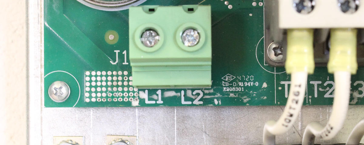
- Connect the line side input leads into the terminal labeled L1 and L2.
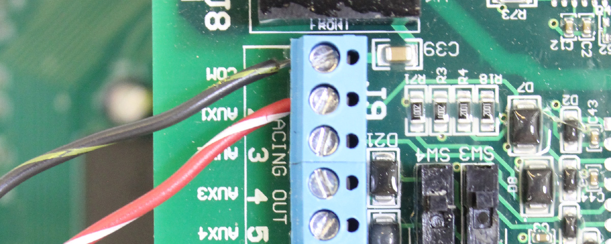
- To add an external run/stop switch, remove the orange jumper wire and connect the switch to AUX1 and COM terminals. Caution: No voltage may be introduced on these terminals. Dry contact only.
Powering up the Phase Perfect®
- Replace the cover and secure using the previously removed screws.
- Turn on the line side breaker and verify screen turns on. Note: Once the unit is fully energized the internal contactor will pull in. Once this occurs a light sizzling noise will be emitted, and is normal.
Download Phase Perfect® Manual
phasetechnologies.com/support/pt
